You will find here a quick how-to about this video : For more details you can watch this 35 minutes video :
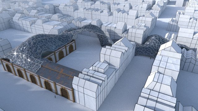
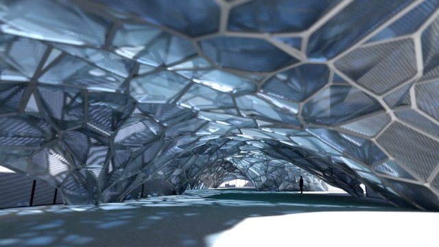
Surrounding buildings :
For the black edges I used the add-on Setup Wire Materials, that you can download here, you will find more info about it here. Once activated you’ll find it in the ToolShelf (raccourci T) :
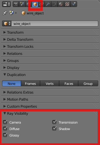
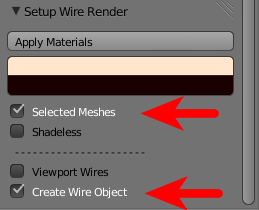 To use it with Cycles you need to tick Create Wire Object to create a new curve object. Remember to tick Selected Meshes too to create the curves only for the selection or it may last for ages. This new Curve can be edited to remove some edges in case you don’t need them. You can the adjust the thickness of the Edges in the Object Data pannel with Bevel Depth.
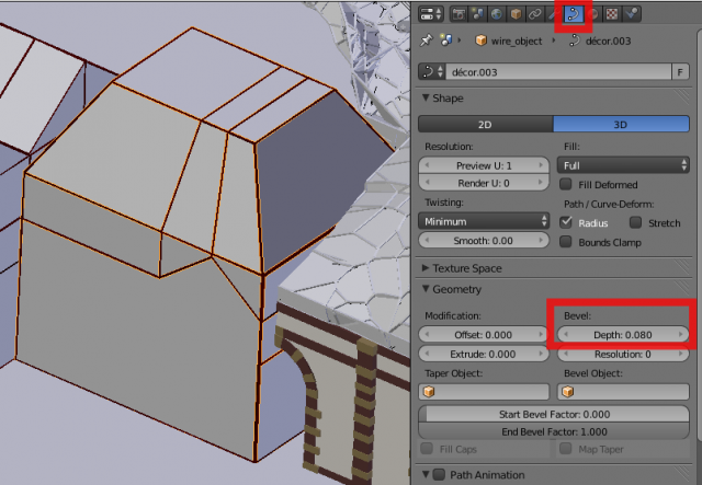 I just used a black diffuse material. You can adjust the Ray Visibility settings in the Object panel so that it doesn’t cast shadows, or even make it invisible but cast shadows (the effect is interesting in some cases).
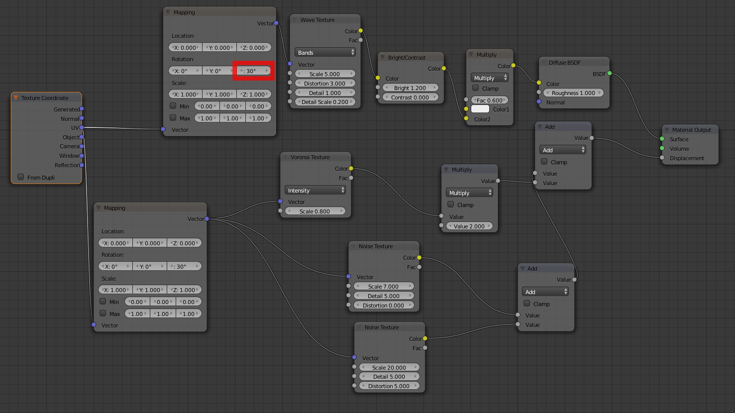
 The buildings must be UV-mapped, bt a quick Cube Projection made the trick here. For the hatches I used a Wave procedural texture, which orientation can be adjusted with the value of the Z angle of the Mapping node. The next nodes allox to adjust the hardness and color of the hatches.For the bum I used Voronoi and Noise textures for Displacement. The node Mapping allow to change the scale of the 3 texture at once.
Fracture a mesh randomly :
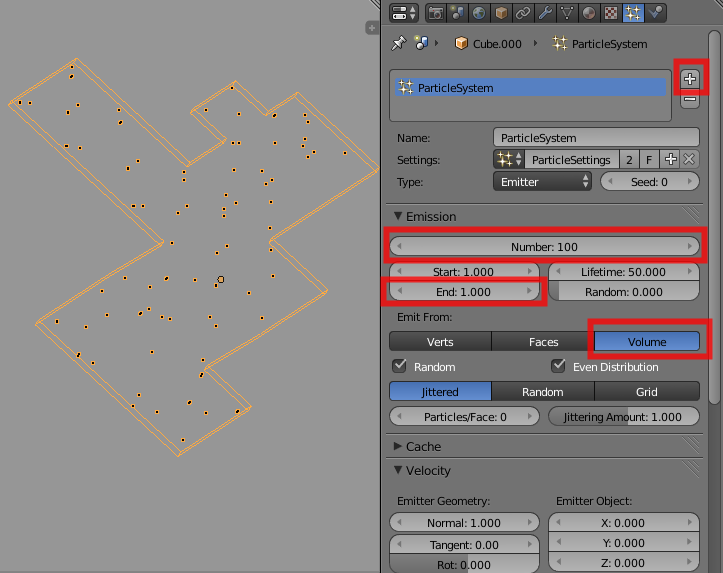
To obtain the random geometry of the roof I use the add-on Cell Fracture which is included in Blender. Once activated you find it in the Toolshelf (T). We use particles to generate the fractures. The settings are almost the default ones except that we want all of them to appear on the first frame ( End at 1) and in the volume instead of only on the faces. The number of particles depend of the size of your mesh.
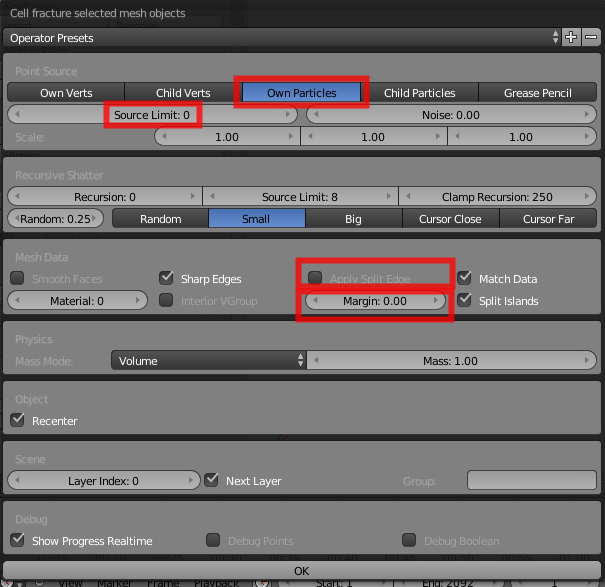
 Once you click on Cell Fracture in the Toolshelf you will see the following settings that we will not change for most of it :
- Own Particles means the fractures are generated by the particles and not the vertices.
- Source Limitt is the maximum number of sources for the fracture. If 0 it will use all the particles.
- Apply Split Edge is ticked by default in the 2.66, you have to untick it to have a plain volume.
- Margin allows a gap between each part, which is necessary for rigid body simulation but in our case it’s better to set it at 0.
 All the parts are created on the next layer, we join them (Ctrl+J) then with useRemove Double with a higher Merge Distance than the default.
Structural deformation with soft body
For detailled explanation, you should read my old tutorial, it is for Blender 2.49, but the settings are the same. So we will:
- Add a Vertex Group (in the Object Data panel): Vertices with a 0 weight will be free to move while vertices with a 1 weight will remain in place. You can also paint those weights in WeightPaint ,ode.
- Soft body simulation in the Physics pannel: you must choose the VertexGroup used. Depending on your project you can adjust the softness of the springs (each edge behaves like a spring) with Push and Pull, and Default is the wheight of the vertices for which you didn’t define a weight
You can the play the animation with the arrow keys to choose the deformed shape you prefer.
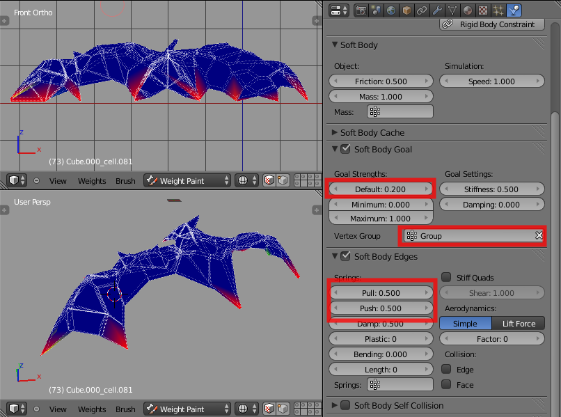 Then, after making a copy of it just in case, you can apply the SoftBody modifier at the frame you choose.
Create the tubular structure
We will use two copies of the object (one used as it for the glass, and the other one for the tubular structure)and we will see two ways of generating the structure.
The simplest one is to select all the faces in Edit Mode and to use Wireframe in the Faces menu(Ctrl+F).Unyick Offset Even or you will have a lot of stranhe peaks and adjust the Thickness. Then you can add a subsurf modifier(if you don’t want a brain-cell type of structure, you can add a Simple Subsurf modifier before the Catmull/Clarck Subsurf modifier).
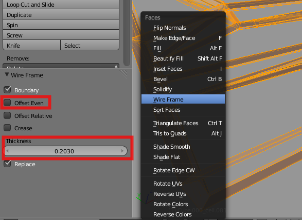
The second method is more complicated and much slower but I prefer the shapes it gives and it is the one I used. You will add a Skin. modifier. It can be very very very slow on complex meshes. But it is very robust, you just have to wait sometimes for hours.And every time you switch between Edit and Object Modes, it recalculate the modifier, so you’d better train yourself and test on simple shapes. The thickness ca be adjusted with Ctrl+A in Edit Mode on the selected Edges (you can input numerical values with the numpad).
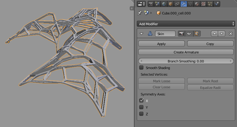
You can the apply the Skin Modifier and eventualy add a Subsurf Modifier. Theoreticaly, you could leave all the modifiers without applying it with the ability to change the original mesh and see the effect on the final design. Unfortunately; you have to apply the modifiers at each step for complex structures.
The translucent polycarbonate material
For this material I just modified the FrozenIce material that you can find on Agus3D’s site, with detailed explanation of how it works. I used a Wave texture as the Fac to mix it qith a glass Shader, to get the lines. A Transparent BSDF shader is mixed with it for the transparent colored shadows.
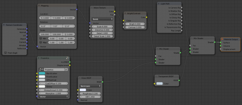
Here you can download the blend file of this project under Creative Commons licence CC-By-SA
fracturesoftvisite